6 Chemical Isolation Construction Considerations
When constructing a cap, there are a number of factors to consider that, if addressed appropriately, will provide increased assurance that the final construction will meet the design criteria (see Sections 3 and 5). This section focuses on the aspects that are related to specifications, preparation, and placement of capping materials.
6.1 Construction Specifications
The level of design detail that is provided in the project plans and specifications, also referred to as construction documents, have a significant impact on the success of cap construction and how the risk and financial responsibility for construction quality is divided among the owner, engineer, and contractor. It is important for the construction documents to provide clear illustrations and descriptions of all project elements, including the following:
- a clear statement of the goals of the remedy and a summary of the overall cap design
- existing site conditions (e.g., bathymetry, surface sediment conditions, debris and obstructions, outfalls, utilities, etc.)
- areal limits of chemical isolation materials placement and related cap elements
- typical detail of the chemical isolation design and related layers of material placed (e.g., base layer, filter layer, erosion protection layer, habitat layer)
- constructed features to facilitate long-term monitoring (if specified)
- specifications for materials and amendments (e.g., type. size, quality, thickness, dosage, etc.)
- material availability
- placement requirements (e.g., sequence, geotechnical, tolerances, etc.)
- permit requirements (e.g., water quality limits and response actions)
- administrative procedures, oversight, and approval steps
- QA/QC (pre- and post-placement)
- health and safety procedures
Construction documents should describe site- and project-specific information to inform the contractor of all conditions and expectations to ensure the highest chance of project success. A clear statement of the goals of the remedy and a summary of the overall cap design (including the CIL) will help to establish a common basis for communication among the contractor, engineer, regulator, owner, and other stakeholders when identifying and reacting to challenging conditions that are expected or unexpected at the start of construction.
Design and construction requirements are generally included in a specifications section on capping or material placement and are typically stated as minimum or maximum acceptable properties, documentation requirements, and construction sequencing. Capping specifications should clearly reference interdependent specification sections within the package, such as dredging, debris removal, and bathymetric surveying. The capping specification section will generally define material and placement requirements for all layers, including geotechnical considerations and construction tolerances.
Specifications should include requirements for materials that are to be used. Material specifications can include the required particle size distribution for sand and aggregate materials that may be used, environmental testing requirements, laboratory testing requirements to verify material properties meet specification requirements, and a list of preapproved manufactured materials or borrow sources. As part of the construction QA/QC program, material specifications should identify testing methods and frequencies that are to be followed by the contractor to document the quality of materials that are provided to the project.
Implementation should be addressed in the specifications. Specifications for implementation should address construction sequencing (i.e., is work required to progress from upstream to downstream or from one area of a site to another), mixing and required dose of amendment materials, the maximum lift thickness, timing restrictions between lifts, timing requirements for placement of erosion protection materials over the chemical isolation materials, progress survey requirements (e.g., frequency and point spacing/density), and QA/QC submittals that are required prior to, during, and following construction.
Tolerances that are stated in the construction specifications for the CIL should be set to accomplish the minimum design requirement (see Sections 3 and 5), with reasonable adjustment for equipment capabilities (see Sections 6.2, 6.3, and 6.4), while staying within the maximum limits (thickness, volume, or aerial extent) that have been established by the project permits.
Finally, construction specifications should clearly require that the contractor provide access to the engineer during work. The specifications should identify specific activities for which the contractor will need to provide assistance to the engineer to satisfy the needs of the construction QA/QC program, with reference to the techniques and frequencies that are anticipated by the engineer. Further discussion of the construction QA/QC program is provided in Section 6.6.
Value engineering should be considered an important step during the design development to ensure that the design is constructable. It may be advisable for the engineer to review construction steps with vendors and contractors. The ultimate goal is to help reduce the potential for significant changes to the design during construction.
6.2 Placement Methods
Construction of a cap can be performed with a wide range of equipment, but each placement method has advantages and disadvantages based primarily on site conditions and materials specified in the design. This section describes a range of equipment and factors that should be evaluated when determining methods and tolerances associated with placement. The focus of this section is on placement over and through the water column, rather than placement in dry conditions (at low water or within a coffer dam that has been dewatered).
✖
- Dry placement is where dewatering or a bypass has been performed that allows for direct placement of materials directly on sediment, without placement through a water column. Much of the same equipment and methods are used for dry placement, though material spread and water current impacts are less of a concern.
- Dry placement of materials allows for direct observation of material placement by equipment operators and by oversight engineers, which can protect against mixing, mud waves, or other disturbance during placement.
- Mud waves and bearing-capacity failures are still a concern for capping during dry placement.
- When working with dry-placement approaches, the construction team should plan extensively for reintroduction of water to the isolation area and the potential for cap materials to be disturbed by the sudden reintroduction of water.
The additional cost to construct appropriate isolation structures or to divert water around the work area should be carefully considered and compared with the constructability advantages.
Material placement methods may be described and defined in the design or project specifications to address certain site conditions, such as swift currents, soft sediments, or permit restrictions on construction methods. It is typical for construction means and methods to be determined by the contractor, who may propose refinements to the placement method or alternative methods. Alternative approaches should be considered to make the best use of prior contractor experiences, though any deviation should be closely evaluated to ensure that the design considerations and permit requirements are fully addressed.
Prescribing the construction means and methods to be used by a contractor is not typical, but it is important to evaluate the placement approach a contractor puts forth in their bid proposal for a project. Table 6-1 summarizes methods that have been implemented on a wide range of capping projects and outlines their relative advantages and disadvantages. This table may be useful when reviewing contractors’ bid proposals or work plans for a specific project.
Table 6-1. Placement approaches and equipment overview
| Equipment | Description | Advantages | Disadvantages |
| Tremie Placement (Figure 6-1) | Discharge of capping material directly from packaging (i.e., bulk bag), dump truck, or the water surface through a pipe (tremie) that allows for placement near the sediment surface. | Low cost, simplicity, ability to place materials at the sediment surface. | Lack of control of thickness tolerance. Low productivity. |
| Excavator Bucket (Figure 6-2) | Use of standard excavator with bucket to spread capping material and place in or through the water column. | Low cost, commonly available, flexible. Can be easily placed on a barge or the shore. | Control of lift thickness is mostly based on the skill of the operator. Water velocity and fall distance significantly affect spread/accuracy. Smaller bucket size gives relatively low production rate. |
| Clamshell—Either Excavator or Drag-Line Mounted (Environmental Bucket) (Figure 6-3) | Bucket with control over center opening. Standard curved bucket or level-cut design bucket. | Can be mounted on an excavator or used with other forms of a crane (e.g., drag line). Improved control with level-cut bucket. Can be easily placed on a barge or the shore. A larger bucket size has a higher production rate compared to the excavator approach. | Control of lift thickness is mostly based on the skill of the operator. Water velocity and fall distance significantly affect spread/accuracy. Drag line can be limited by overhead access. |
| Conveyed Aggregate Delivery or Stone Slinger (Figure 6-4) | Dump truck with live-bottom conveyor that “slings” material as it is unloaded from the truck bed. The rear conveyor is articulated and has an approximately 30-degree arc for placement of material. | Low cost and commonly available equipment. Can be placed on a barge or the shore. Provides high productivity and uniform distribution of capping material with a spread of approximately 60 feet. | Placement speed typically limited by the time needed to reload the slinger. Requires more equipment to transport capping material to maintain productivity. Impact velocity in shallow soft sediments may lead to resuspension, mixing, or mud wave issues. |
| TeleBelt® (Putzmeister) (Figure 6-5) | Telescoping and articulated conveyor system has an extended reach over the placement area. | Provides high productivity and a high level of control of capping material being placed. Provides uniform distribution of capping material over a distance of approximately 120 feet. Can be placed on a barge or the shore. | Higher cost and less commonly available equipment requires a dedicated operator. Impact velocity in shallow soft sediments may lead to resuspension, mixing, or mud wave issues. |
| Aggregate Hopper (Figure 6-6) | Aggregate or Portland cement hopper suspended by crane or helicopter. | Simple equipment and precise placement. Can be used from the shore or a barge. | The need to refill often lowers production rate. Must operate lever to discharge material. Difficult to obtain uniform placement through the water. |
| Proprietary Placement Systems (Figure 6-7, Figure 6-8) | Broadcast spreader barge and hydraulic barge-based spreader. | Provides high productivity and a high level of control of capping material being placed. Provides uniform distribution of capping material within controlled “moon pool” at the placement barge. | Higher cost, only available from selected contractors. Equipment is barge-based and does not accommodate placement from the shoreline. |
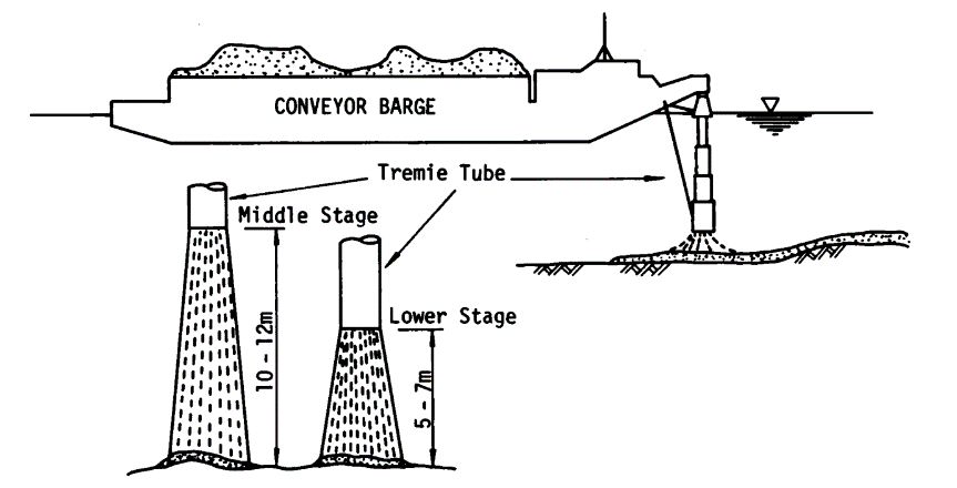
Figure 6–1. Tremie placement.
Source: USACE
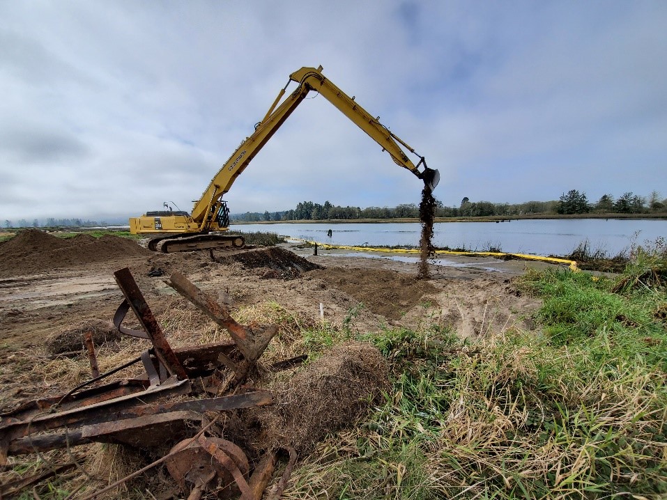
Figure 6–2. Excavator bucket.
Source: Maul Foster & Alongi, Inc. Used with Permission.
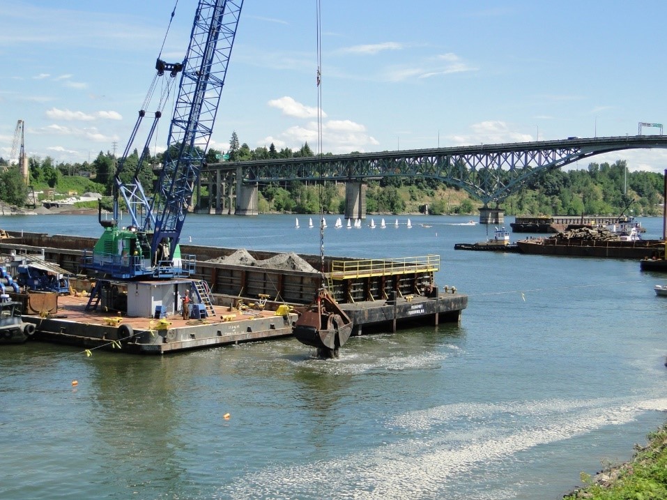
Figure 6–3. Clamshell bucket.
Source: Maul Foster & Alongi, Inc. Used with Permission.
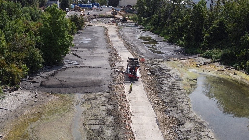
Figure 6–4. Conveyed aggregate delivery.
Source: Maul Foster & Alongi, Inc. Used with Permission.
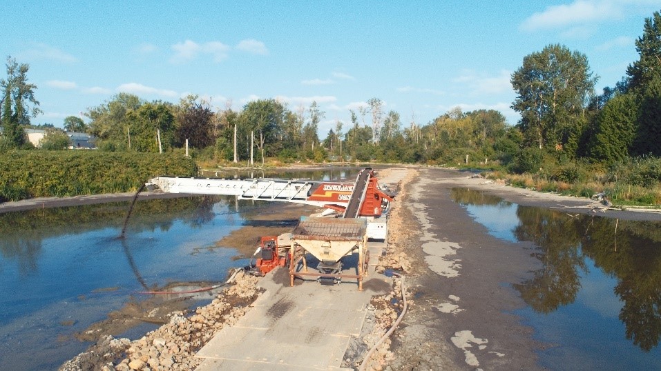
Figure 6–5. TeleBelt®.
Source: Maul Foster & Alongi, Inc. Used with Permission.
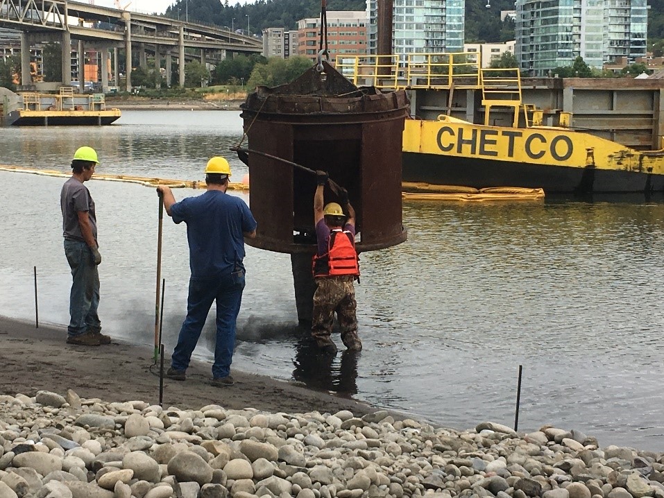
Figure 6–6. Aggregate hopper.
Source: Oregon Department of Environmental Quality. Used with Permission.

Figure 6-7. Broadcast spreader system.
Source: J.F. Brennan Company, Inc. Used with Permission.
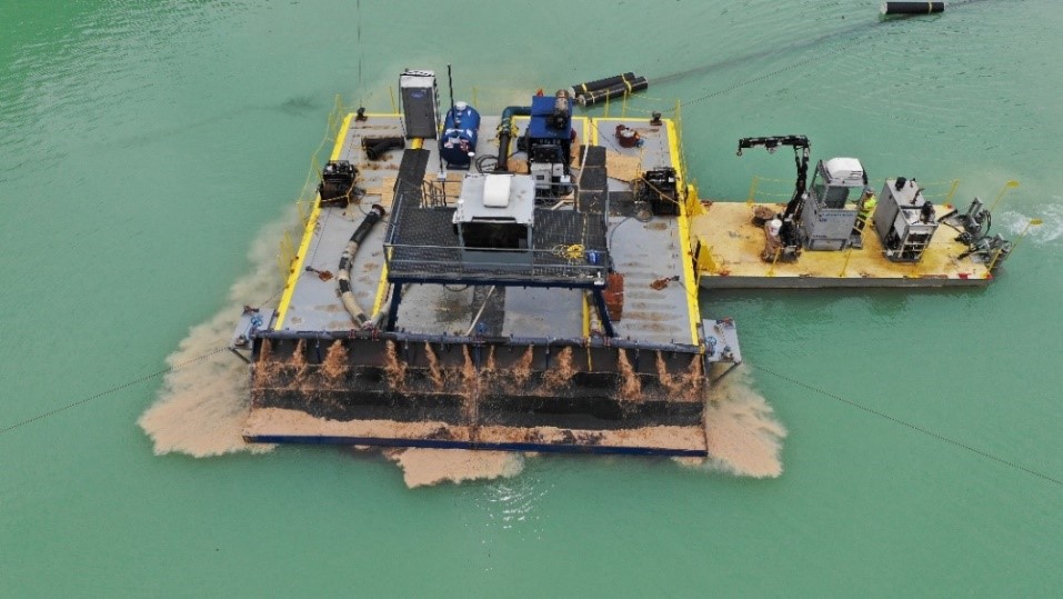
Figure 6-8. Hydraulic capping system.
Source: Sevenson Environmental Services Inc. Used with Permission.
A range of construction-related factors relevant to placement should also be taken into consideration. Some of these relate directly to the specific placement equipment used, but each can have an impact on the overall quality of the installation. Table 6-2 presents a list of placement-related issues with descriptive information and comments regarding best management practices.
Table 6–2. Placement-related considerations
| Placement Challenge | Considerations |
| Equipment Placement Accuracy and Tracking |
|
| Turbidity Controls |
|
| Material Loss During Placement |
|
| Installation of Manufactured Materials and Mattresses |
|
| Placement of Multilayer Caps |
|
Acronyms and Abbreviations:
RTK = real-time kinematic
GAC = granular activated carbon
GPS = global positioning system
6.3 Amendment Dosing
In circumstances where the chemical isolation design includes the addition of an amendment, the control over amendment dosing, including setting tolerances for the designed amendment dose, is an important construction consideration. The designed dosage of amendments is typically established using a modeling approach as discussed in Section 5, but can also be informed by site-specific treatability testing and values obtained from literature. During construction, it is important to have a good understanding of the required amendment dosing tolerances and have mechanisms is place that ensure the designed amendment dosage and assumed uniform distribution of the amendment are achieved so the chemical isolation function performs as designed. This includes implementing a post-construction QA/QC program (Section 6.6) to verify the proper dose of amendment, proper mixing (if required), and the proper vertical and horizontal distribution of the amendment within the cap.
Amended cap layers are typically designed with sand as the primary cap material, with the amendment and sand mixed on site during construction. Amendments and sand can be mixed in a variety of different ways, including bulk, continuous, or batch mixing. Typically, the implementing contractor will establish the means and methods for mixing the materials. Prior to placement, the proper mixing and uniformity of the materials should be verified. Verification should also be conducted prior to, and periodically throughout, the use of the mixed-cap material when constructing the cap. Verification of mixing should include collecting samples to confirm that the amendment dosage has been met within the specified tolerances, the material is well mixed (i.e., there is even distribution of the amendment throughout the sample), and the integrity of the materials has not been degraded by the mixing process. The methodology for verification will vary based on the amendment and form of the amendment3.
When developing requirements for amendment dosing and QA/QC protocols it is important to consider the units of measurement that will be used to verify dosing (e.g., by weight or by volume) and how measurements will be collected in the field. If the dosing requirement is specified as a percent by dry weight compared to the total capping layer (i.e., 5% amendment of the total CIL) it is important to identify the unit weight of material assumed when developing the specification and consider how the specification may change if field conditions of the material are different from what was assumed when developing the specification. For example, sand is a common material that is amended for a CIL and can have a wide range of particle sizes and moisture content, leading to a relatively wide variation in bulk density. It is important to consider how the amendment dosing requirement may be impacted if conditions of material in the field are not consistent with what was assumed in the design specifications. Additionally, some amendments, such as GAC, may need to be manipulated (e.g., it may be necessary to wet or water-saturate GAC) before being mixed into the primary material being used for the CIL, which can impact the dosing calculation. It is important to consider these types of conditions when conducting QA/QC testing of amendment dosing in the field and how they may impact the comparison of results to the dosing specification. When possible, it is recommended that QA/QC testing be performed in the field and real-time feedback be provided to the implementing contractor to ensure proper dose and tolerances are achieved prior to placement of material.
Table 6-3 below outlines some amendment-specific considerations for commonly used amendments.
Table 6–3. Amendment-specific considerations
| Amendment | Dosing Considerations |
| GAC |
|
| PAC |
|
| Granular Organophilic Clay |
|
| Organophilic Coated Aggregate Particle |
|
Acronyms and Abbreviations:
CIL = chemical isolation layer
GAC = granular activated carbon
PAC = powdered activated carbon
QA/QC = quality assurance and quality control
6.4 Design and Construction Tolerances
The tolerance or the allowable variation that should be considered for cap construction relate directly to the amount of material that is required to ensure the minimum performance of the design (design tolerance), and the ability of equipment to accurately place materials (equipment placement tolerance). Design tolerances include both the layer thickness tolerance and the amendment dose tolerance.
6.4.1 Design Tolerance – Thickness
The design thickness tolerance is typically expressed in terms of a measurement for the desired layer thickness (e.g., 6 inches), as presented in Sections 3 and 5, with a range that includes aminimum and maximum variation (e.g., +/- 1 inch) or with a zero minus tolerance and a maximum overplacement tolerance (e.g., minus zero, + 3 inches). In some cases, these tolerances may be applied to specific percentages of a capped area (e.g., minus zero, +3 inches over 90% of the cap area, with a total not to exceed +6 inches). Design tolerances must be established by the designer in a way that ensures the minimum design objectives are met, that the layer is constructable with the anticipated equipment, that material quantities and project costs are controlled, and that permit limitations on fill volume or elevation are not exceeded. The objective is to provide the contractor with some level of flexibility to achieve the design thickness and enable more reliable placement and determination of required material quantities.
6.4.2 Design Tolerance – Amendment Dose
The design dosage of amendments is typically established through treatability studies (to determine adsorption data) and/or a modeling approach as outlined in Section 5 and may be expressed in the specifications in a number of ways. For example, the amount of amendment is often provided as a minimum percentage by weight of the capping layer (e.g., 5% of a 6-inch sand layer). Alternatively, it can be expressed as a mass of amendment per area of cap (e.g., 2 pounds per square foot within a 6-inch sand layer). Less commonly, an upper tolerance may be specified, possibly to avoid impacting geotechnical properties of placed materials or to manage project cost. For construction, it is important to have strong QA/QC procedures established in advance to ensure the design amendment dose is provided and assumptions regarding the uniformity of distribution of the amendment within the cap layer are met.
6.4.3 Equipment Placement Tolerance
Different types of equipment used to place caps have varying capabilities for achieving uniform thickness of the as-placed capping materials. The equipment placement tolerance is generally determined by the contractor and is based on the relative ability of a given placement approach or type of equipment to achieve an average uniformity of thickness during application of materials (see Table 6-1).
The equipment placement tolerance is generally determined by the contractor, who evaluates expected equipment placement capabilities based on the type of equipment and skill of the operator. The contractor then compares this expected or anticipated outcome or result to the thickness tolerance requirements. From this, the contractor determines the quantity of capping material needed to construct the work in a manner that will meet the design objectives. For example, if a design calls for a 6-inch-thick sand layer amended with 5% GAC, with a minus zero-inch thickness tolerance (meaning the layer cannot be less than 6 inches thick anywhere), the contractor may evaluate the site setting (e.g., slope, water velocity, and water depth) and available equipment and manpower and determine that placement by excavator is the most cost-effective approach. They may also conclude that in order to achieve the necessary 6-inch thickness and to account for material losses during placement (see Table 6-3), an additional 3 inches (or 50%) of overplacement is required to meet the thickness specification.
In this regard, the thickness tolerance and methods to achieve the amendment tolerance will impact decisions made by the contractor when evaluating both equipment and placement approaches. The quantity of material and the equipment cost (and/or availability) will be determined by the contractor, which will impact the bid price to perform the capping as designed.
Another important factor related directly to tolerance is who takes on the financial responsibility and risk to ensure that the specified quantity of amendment is placed and that uniform vertical and horizontal distribution of amendment materials within the cap is achieved. Using the above example, if the contractor is responsible not only for layer thickness but also for the uniform distribution of the GAC within this 6-inch layer, then they may make the decision that, to achieve a minimum 5% GAC content, they need to increase the GAC dose or loading of GAC within the sand prior to placement (due to potential losses or nonuniformity resulting from separation or loss of GAC during placement). In this regard, both design and the requirements for post-construction QC can have a significant impact on material quantity, placement, equipment selection, and construction cost.
6.5 Site-Specific Factors Affecting Construction
The location and physical setting of the proposed cap area will have a major influence on the site-specific design and, just as importantly, on the constructability of the planned design. When developing the construction program for a CIL, the project design team should consider the nature of the water body, active water uses, site access, physical and engineering characteristics of the site, and permit conditions. The QA monitoring and sampling program may require more frequent monitoring in more challenging settings. Because of the frequently turbulent and unexpected conditions during cap construction, every effort should be made to ensure that the engineer and construction manager have collaborative interactions. The engineer, construction manager, and regulatory agencies (as necessary) should participate in the development and selection of potential response measures. At all times, communication between the engineer and construction manager is paramount to identify changing site conditions and collaborate on corrective measures or construction or design modifications. Table 6-4 lists the site-specific factors that should be adequately anticipated and addressed while constructing a cap.
Table 6–4. Important considerations for planning and construction
| Factor | Considerations |
| Water Energy–Level Profile | High-energy water environments may cause cap material drifting, which may be addressed by temporary water diversion, the release of cap material near the mudline, or other contractor-recommended approaches. |
| Mud Waves | Cap material placement may induce mud waves away from or through the placed material in all directions. Therefore, where necessary, placement of material in thin lifts from the outer extent toward shore is recommended. |
| Slopes | Placed cap materials may be unstable if not supported, so placement of material should proceed from the lowest (stable) elevation to the highest. Additional slope stability measures can be implemented where necessary. |
| Shoreline Transition | Physical integration (e.g., mixing, raking) of nonarmored chemical isolation material may be necessary for contiguous isolation from upland to in-water sections of a cap. |
| Physical Stability of Base Sediment | CIL requires a physically stable support base for continuity and may require placement of a base layer for mixing with underlying sediments to improve its physical stability. |
| Site Ownership | Cap design may be complicated by access issues. Early design attention must be given to land ownership, access, and current and future uses. |
| Upland Support Area | Staging areas are required for delivery and storage of capping materials before placement. |
| Proximal Dredging Operations | Drifting of fine sediment from proximal dredging activities may intermix with chemical isolation materials. Turbidity curtains installed during cap placement or appropriate sequencing of remediation work may be required and can mitigate these impacts. |
| Overhead Infrastructure | Overhead infrastructure such as bridges and power and communication wires may limit the use of some types of placement equipment such as clamshell buckets and cranes. |
| Concentrated/Focused Groundwater Discharge Area | Seeps associated with high rates of groundwater discharge may erode capping materials. Reasonable efforts should be made to identify seeps prior to construction so that subsurface pressures may be relieved through the installation of drains, plugs, or other mechanisms. |
| Unexpected Debris | Unexpected debris such as abandoned pilings could interfere with chemical isolation material placement. Use of alternative materials or removal maybe considered. |
| Combined Sewer Overflow and Stormwater Outfalls | Erosion of chemical isolation material is possible unless outfall flow energy is dissipated (e.g., concrete spillways, energy dissipation). |
| Coordination with Port Authority, U.S. Coast Guard | Shipping lanes and security issues may delay installation of capping materials unless resolved beforehand. Attention to and coordination with navigational authorities should be conducted early in the design process. |
| NAPL | NAPL may saturate chemical isolation material or reduce the capacity of the adsorptive layer. The unexpected presence of NAPL may require significant contingency measures or rework of specific design measures. |
| Gas Ebullition | Release of gas buildup may disrupt chemical isolation material continuity. Gas generation in subsurface layers and ebullition should be well understood early in the design process. |
| Traffic Control, Noise, Dust | Shipment of chemical isolation or armor materials by large trucks may interfere with quality of life within the immediate vicinity of the project (see Appendix D). |
| In-Water Work Window / Fish Window | State or federal agencies may preclude in-water work during certain months of the year to protect spawning or the migration of sensitive species. Special design and construction method considerations may be required to accommodate work restrictions. |
In addition to the site-specific considerations discussed above, other conditions and potentials must be considered during construction, as listed in Sections 6.5.1 through 6.5.5. It is most prudent for these conditions to have been planned for during the design phase; however, unexpected conditions are often encountered during construction and must be accommodated. The following subsections describe examples of site conditions or events that may not have been anticipated during the design phase for which contingencies must be developed during the construction phase.
6.5.1 Scheduling and Sequencing
Construction scheduling and sequencing may need to be addressed or modified if site conditions change or become unfavorable for successful materials installation. For instance, as noted above, if mixing or resuspension is observed during dredging that may impact the construction area, changes in the sequence or schedule may minimize these impacts. Similarly, if materials placed through the water column are staying in suspension longer than anticipated, additional time may be required between successive lifts before QA/QC can be performed or before approval for additional placement.
6.5.2 Addressing Mixing with Underlying Sediments
Construction equipment selection and cap placement methods may need to be adjusted to avoid unexpected mixing of cap materials and underlying sediments during placement. Mixing contaminated surface sediment with the initial CIL layer during placement can reduce the effective thickness of the overall CIL, reducing the anticipated cap life. During construction, if excessive or unanticipated mixing is detected, adjustments may be made by altering the placement method (e.g., lowering the placement bucket through the water column), placing additional cap material until the mixing ceases, reducing the thickness of individual lifts to minimize the mass impacting the sediment surface at one time, or adding a base layer or geotextile. Similarly, construction equipment selection and barge deployment may also require modification during construction. If the use of barge spuds or other in-water anchorages becomes necessary, care must be taken to avoid penetration or disturbance of previously installed cap materials to minimize mixing of contaminated sediments and CIL materials. In either case, construction QA/QC checks, such as demonstration pilots or the collection of sediment cores, should be made early on to evaluate the extent to which mixing may be occurring and whether an adjustment in the placement approach is needed.
6.5.3 Encountering NAPL Deposits
Prior to beginning construction, identifiable NAPL deposits should be well defined and design components included to properly handle such material. Nevertheless, even with proper preparation, NAPL deposits may appear during construction activities and must be addressed to maintain chemical isolation performance. In such instances, potential contingency measures include focused removal, installation of additional adsorptive materials prior to cap placement, or placement of additional sacrificial cap material to sorb expressed NAPL and to provide physical separation between the NAPL impacts and the clean capping material. In any event, precautionary measures (e.g., sorptive pads, oil booms) should be considered during construction to immediately respond to the presence of NAPL or any releases.
6.5.4 Proximal Dredging Operations
Nearby dredging or other sources of suspended materials (e.g., storm runoff, flooding), may have the potential to mix with CIL materials or recontaminate the cap surface. Although coordination should be handled during the design and construction-planning phases, there is always the potential for unanticipated construction activities adjacent to the cap construction location. Additional corrective measures may be necessary if there are unavoidable impacts from other nearby turbidity-generating activities. Installation of materials can be coordinated or rescheduled to ensure adequate equipment spacing and sequencing of activities to minimize impacts of adjacent in-water activities. Additional control measures (e.g., deflection walls, turbidity curtains) can be deployed to limit the transport of suspended materials into the installation areas.
6.5.5 Material Availability
Construction specifications and regulatory requirements related to construction materials should be determined during the design stage. This should include regulatory approvals and testing requirements, chemical criteria, TOC requirements (if applicable), physical properties, and estimated quantities. These specifications should take into consideration the availability and cost-effectiveness of the specified materials or products. Use of standard material specifications from ASTM, the American Association of State Highway and Transportation Officials, or state or local transportation or public works departments can improve the likelihood of identifying suitable materials. Similarly, specification of off-the-shelf amendment products and manufactured materials and riprap gradations available from local quarries should be considered. Design may also include the evaluation of potential cap material sources as needed. Evaluation of potential cap material sources during the design stage typically includes identifying candidate sources, their distance from the site, production capacity versus project needs, and transport methods. Depending on the quantity and materials, physical and chemical testing of potential borrow sources during the design stage may also be conducted. Early testing of potential sources may be necessary in areas where background levels of contaminants are common; this allows time for additional evaluation, regulatory approval, or identification of alternate sources.
Cap material specifications for manufactured products, including amendments, should identify multiple acceptable products from specific vendors or allow for equivalents or alternatives. This gives contractors the flexibility to identify timelines for production and supply of any purchased materials in advance of construction. In some cases, it may become necessary to procure materials with long lead times in advance of contractor selection. As with borrow materials, the availability of manufactured cap materials versus project needs should be evaluated during the design phase.
During construction, cap material testing to confirm compliance with specifications and regulatory requirements is required and can impact construction scheduling. Adequate evaluation of cap materials and borrow sources prior to construction and timely testing of materials during construction are necessary to avoid construction delays. The project plan should address the available quantity of material, transport time, staging area required on site, and the time required for confirmation sampling or testing to meet the capping construction schedule.
6.6 Construction Quality Control and Quality Assurance Measures
Proper construction of the CIL relies on attention to the QA/QC measures that are specified for the project. These measures are outlined in a construction QA plan or a construction QA/QC plan that is prepared in advance by the engineer. In the context of construction, QA is the engineer’s (or owner’s) system or process to assure end product quality by monitoring contractor activities, reviewing contractor QC documentation, performing independent testing, and inspecting contractor work. QC is the contractor’s system to manage, control, and document materials and activities to ensure compliance with the contract. A good quality management program will outline detailed QA and QC methods and provide appropriate documentation to be used to demonstrate that the cap is constructed in conformance with the design. Documentation of the quality of the constructed cap is an important baseline as the project moves from construction to long-term performance monitoring and for use if troubleshooting is needed in the future.
6.6.1 QA/QC of Materials Prior to Placement
Assessing the quality of materials that are delivered to the project and providing proper management in the steps immediately prior to placement are critical engineering oversight processes for ensuring that materials meeting design objectives will be supplied to the project. Thorough documentation of these procedures may be important for later reference during evaluation of the CIL performance or later troubleshooting efforts.
For bulk materials used to construct a capping layer, identification of the source of materials should be made by the project owner or by the contractor, depending on the availability of clean materials. If the cap material source is identified by the contractor, the engineer must have sufficient time to sample the material and verify that the proposed source satisfies the chemical and physical specifications. Sufficient time should be allowed for samples to be obtained and analyzed. Sampling methodologies should be considered to verify the average quality of sources for large quantities of materials, such as multiple grab or composite samples that are randomly distributed or incremental sampling approaches (ASTM Standards for bulk material sampling are recommended). Preconstruction analysis of the source material samples should evaluate physical and chemical parameters (e.g., grain size, specific gravity, fraction of organic carbon or TOC) and contaminant concentrations (e.g., site-specific COCs, contaminants associated with local industrial activities, naturally occurring elements that may be elevated because of known regional background levels, and other constituents that may influence fate and transport properties within the cap). An evaluation of any significant deviations from the project specifications should consider how long-term chemical isolation performance will be influenced. This may include additional cap model evaluations using the updated cap material properties or further geotechnical evaluation. Approval of the source(s) to be used for the cap material should be documented for the project.
The quality of required amendments should also be evaluated prior to and during delivery to the project site. Assessment of amendments prior to construction should focus on verifying that the proposed material information from the manufacturer meets the project specifications. Review of the manufacturer product specification sheets may include material type, particle size, density, adsorptive capacity, etc. Evaluation of the proposed amendment products may also include verification of manufacturer production and delivery capacity, transportation methods, appropriate packaging, and other project-specific concerns. Chemical analysis (for site-specific COCs) of amendment samples and periodic testing of amendments delivered to the site may be desirable for documenting the initial condition of the amendments.
Once the quality of the materials that are being delivered to the site have been verified and documented, it is important to consider how to best protect the materials prior to placement. Strategies for protecting materials depend on the nature and quantity of the material being stored. Common strategies are listed in Table 6-5 below.
Table 6–5. Material management–related considerations
| Management Category | Considerations |
| Large Quantity Natural Materials (i.e., Sand, Silt, Gravel) |
|
| Manufactured Products |
|
| Geosynthetic Materials (Geotextiles, Geosynthetic Mats, etc.) |
|
The addition of an amendment to create the CIL materials is discussed in detail in Section 6.3. QA/QC procedures for mixing the amendments into the CIL may consist of a combination of visual and laboratory testing, as described below:
- Weight records: Whether mixed on site or mixed at an off-site mixing plant, it is important to record the volume and weight of the amendment material and the quantity of the cap material that are being mixed for the batch. The engineer should verify that the quantities listed on the mix records will achieve the minimum amendment percentage specified in the design. Weight records are the primary line of evidence that are relied upon to demonstrate that satisfactory quantities of product have been delivered.
- Visual observation: A visual inspection of the mixed product should be conducted by the engineer to verify that the material appears to be a homogeneous mix based on overall color and apparent granularity.
- Laboratory testing: If necessary, grab samples of the mixed product batches can be sent to geotechnical laboratories for assessment of grain size, density, particle size distribution, or other analyses that may help to confirm that exact dosing requirements have been satisfied.
It is important to recognize that transport and handling of an amended capping material (sand mixed with amendment) may result in separation of the product due to differing grain size and density. Periodic visual inspection and/or laboratory evaluation may be needed to assess the mix immediately prior to placement and verify that it meets or exceeds minimum design standards. Preproduction demonstration of product delivery and placement may be an important step to allow the engineer to verify that the mixture is being effectively deployed prior to allowing the contractor to move into production placement.
6.6.2 QA/QC of As-Placed Capping Materials
In addition to the preconstruction QA/QC steps discussed above, during- and post-construction QA/QC activities are imperative to increase the probability of a successful installation of capping materials. During construction, QA/QC checks can be used to inform possible modifications in material selection or construction methods, and post-construction checks can demonstrate completion of the intended design. Primary construction QA/QC steps include demonstrating the extent and thickness of cap placement (which can be compiled in a weight-of-evidence approach to demonstrate placement extent and thicknesses) and post-placement verification of amendment content and uniformity where appropriate.
6.6.2.1 Chemical Isolation Layer Thickness
Verifying the thickness of the placed chemical isolation materials is essential in demonstrating that the chemical isolation performance will be consistent with the design. The thickness of cap layers is typically assessed through either bathymetric survey or through physical observation. It is important to consider the chemical isolation materials, design thickness (and tolerances), and site conditions when selecting thickness verification methods. In many cases, it may be prudent to use a combination of bathymetric survey and physical measurement to present a weight-of-evidence approach to demonstrating successful placement of capping materials.
Bathymetric survey is an appropriate verification method when the designed layer thicknesses exceed the resolution of the survey, which are typically 0.25 to 0.5 feet. The remote and conventional survey methods discussed below can be used to illustrate the presence and extent of newly installed chemical isolation materials, provided reliable preconstruction surveys are available:
- Conventional topographic survey methods can be used to measure elevation changes and create a bathymetric surface across the placement area, as well as just beyond the area to demonstrate the apparent edge of material placement. Conventional topographic surveys can be performed on foot while wading in shallow waters. They can also be performed from the water surface on a barge or vessel; however, in deeper water, or with unfavorable wind or wave conditions, it can be challenging to get reliable topographic results.
- Hydrographic survey systems that integrate acoustic sonar systems with carrier-phase GPS positioning systems can also be used to create bathymetric surfaces and assess the condition of the top of the as-placed capping materials. Single- and multi-beam survey systems are towed across the water surface above the installed materials to record continuous data correlating position and elevation. Single-beam equipment is most often deployed in shallower water but returns a single linear path of data. Multi-beam equipment data can be used in greater depths and areas and covers a greater breadth of a capping layer surface. Guidance for hydrographic survey methods is available from the USACE (2013).
Post-placement elevations are compared to preplacement elevations to create an estimate of placement extents and thicknesses. Any of the results of the survey methods introduced below should be used with caution as material installation may induce consolidation of underlying materials that skews or obscures survey results or makes related conclusions challenging. It is also important to understand the relative sensitivity of measurement systems in comparison to layer thickness placed. In some situations, a subbottom profiler may be deployed with the goal of distinguishing between different material horizons (e.g., CIL and native sediment) in cross section, which might provide evidence of physical mixing at the material horizon and a measure of the apparent thickness of the installed CIL regardless of any local consolidation.
Common means of assessing thicknesses can also be deployed in certain conditions and can provide additional support during and following construction related to the success of the installation. Common means of physically assessing installed material thicknesses include the following:
- Construction contractor demonstration and records of the mass and volume of material imported, mixed, and placed can be used to assist with the interpretation of post-construction cap thickness and assure that cap placement criteria have been met.
- Retrievable settlement pans made of sheet metal or plexiglass can be lowered to the sediment surface prior to material placement. The settlement pans collect material as it falls into place either on top of the native sediment or on interim lifts. The pan can then be retrieved, and the apparent material thickness measured as an analog to actual cap material thicknesses. A key benefit is that the use of pans prevents intermixing of materials with underlying sediment, providing a more accurate indication of as-placed thickness. During construction, the contractor should not know the location of the settlement pans, since the results generated from these techniques are more prone to manipulation by the contractor (i.e., overplacing material around the settlement pans while minimizing placement in other areas).
- Settlement plates or platforms with rigid and metered stickups can be installed prior to material installation. Following placement, the stickup, similar to a grade stake, can be monitored either remotely or via diver inspection, and the apparent thickness of the material placed can be recorded.
- Sediment cores can be obtained by boat or by divers for evaluation at the surface. It is preferable to use large-diameter clam guns with acetate liners to obtain samples of individual lifts with little disturbance of the native as-placed layers. Cores can be visually inspected for quality, thickness, and evidence of mixing at the material interface, and samples can be taken for laboratory analysis. Where soft sediments exist or a mixing layer is present, determining the base of the cap layer can be challenging with core samples.
- SPI can be used in applications where relatively thin layers (3 to 4 inches) are being placed. The SPI camera penetrates the sediment or cap surface and takes a cross-sectional picture with a scaled image from which the apparent thickness can be estimated.
All of these assessments of approximate layer thickness can be deployed in conjunction with the wider-area survey methods discussed above. These particular methods have the advantage of being direct measurements of thickness, rather than elevation, and are independent of potential consolidation.
6.6.2.2. Cap Material Composition and Uniformity
It is important to evaluate capping materials both before and after placement. Samples of placed material can be obtained from sediment cores (discussed above) for laboratory analysis to assess chemical concentrations and the amendment quantities in the capping materials after placement. Challenges often exist when analyzing materials with amendments. These can be difficult to assess for achievement of prescribed amendment fractions, but a variety of lines of evidence can be employed. Although there are some promising smaller-scale proprietary means of assessing amendment content in material samples, there are no established and widely accepted protocols.
Throughout construction, close attention to amendment material mixing (e.g., sand and activated carbon) is necessary, particularly the mass of each component being added to the mix. The goal is to verify that the original mix is as close to the specification as possible. Once mixed, it can be nearly impossible to visually identify the individual components; however, visual observation tends to be the primary means of identifying the presence of the amendment and general homogeneity of the amendment within the material mixture. To evaluate a mix prior to placement, visual observations can be made of samples pulled from the mix to assess the presence of the amendment and homogeneity of the mix. Careful QC of mix weights of capping components is necessary to ensure the correct weight or dose of amendment is present.4
Where weighted proprietary amendments (such as AquaGate+®PAC or SediMite™) are mixed with sand to create a CIL, preplacement separation can be performed to validate amendment dose based on physical particle size separation. With regard to post-placement chemical isolation material sampling, settling pans and sediment cores (discussed above) can be used to visually observe the presence of amendment materials. Where powder materials are used as an amendment, as-placed materials can be sampled and oven dried, and physical separation can be performed to verify as-placed amendment content. Finally, SPI images can be used for visual observation of in-place capping materials.
The QA/QC methods discussed above can be successful ways to assess the composition of the in-place CIL. Typically, cap performance models assume a uniform distribution of the amendment material (e.g., activated carbon) throughout the cap layer; however, such uniformity can be difficult to achieve during construction. Visual evaluation of the uniformity of the in-place cap material can be made using settlement pans, SPI images, or cores, but quantitative methods of evaluating uniformity are not yet widely used. Nonuniform distribution can have a significant adverse impact on the performance of the cap, and based on visual observations, modification of the construction methods may be warranted.
6.6.3 Completion Reporting
Following the completion of construction, a completion report documenting the means and methods used for cap construction and associated construction QA/QC requirements (e.g., daily and/or weekly construction QA reports and as-built documentation) should be prepared. This report should include the deviations from the design requirements (e.g., cap material modifications, over or underplacement, etc.) and document whether the design objectives have been achieved. Additional details in this report may include a photolog documenting the various construction activities, final material specifications, construction-related data (e.g., field data, survey data, laboratory data, etc.), and post-construction inspection report.
3 It is typical for contractors to select the means and methods for verification, but the engineer may opt to require specific means or methods for verification of proven approaches or to address manufacturer requirements.
4 A direct activated carbon measurement method is described in Grossman and Ghosh (2009).

